Top of Site > Company Information > Patents for Clamps > Denney
| Patent Number | 357 524 |
| Date Applied For | 1886 Oct 4 |
| Date Issued | 1887 Feb 8 |
| Issued to | William H. Denney |
| Location | Lancaster PA |
| Current Class/ subclass | 269/219,258, D8/72 |
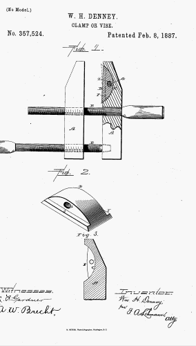
The illustration has 3 figures: the whole clamp, the adjustable piece, and the recess in the stopped jaw. Oddly, the two witnesses to the drawing are the not the two witnesses to the specification.
Quoting the second and third paragraphs of the specification:
My invention relates to an improvement in clamps or vices; and it consists in the combination of one of the jaws, which has a concave recess formed in the inner side of its upper end, with an adjustable slotted bearing piece, which is convex on its rear side, provided with bearing flanges on its opposite sides and placed in the recess in the jaw, and a pivotal pin, which is passed through both jaw and bearing piece, as will be more fully described hereinafter.
The object of my invention is to provide an adjustable bearing piece for one or both jaws of a clamp or vise, and which turns upon a pivot of its own, so that it will automatically adjust itself to a straight or flat object between the jaws in case they do not draw parallel.
last revised and validated
Copyright © 1996- Wooden Clamp Journal